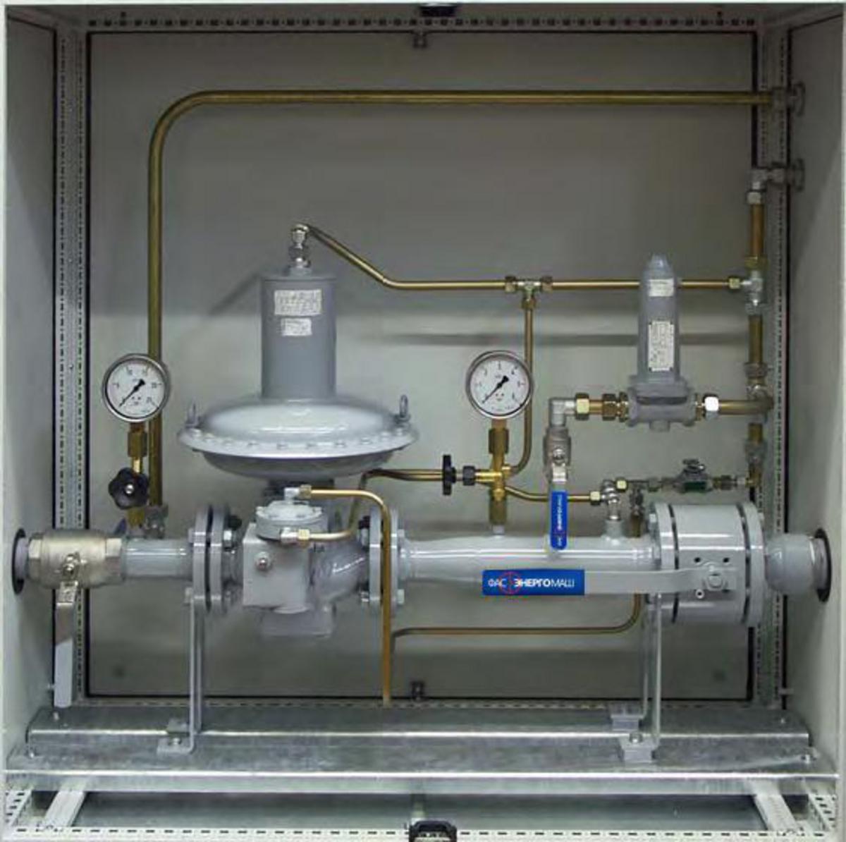
Cabinet Type Gas Control & Distribution Unit FEM GRPSh/5
A control and distribution system of FAS units is configured to monitor and regulate pressure as well as prevent against unacceptable pressure load on valves and devices connected to the system after the control and distribution unit. It is mounted in a steel galvanized and painted cabinet sized 1,200x400x1,200 mm. Input: DN50; output: DN80.
Basic Components
- Pressure regulator, DN50, PN16, with a safety shut-off valve for upper and lower shut-off. Inlet pressure: up to 16 bar; outlet pressure: 130 mbar to 1.1 bar. The outlet pressure is set for 1,000 mbar. Safety relief valve: upper shut-off – 1,250 mbar; lower shut-off – 220 mbar.
- Safety bleeder valve, 1"NPT, PN16, G1"; servo drive casing of GGG40, DIN 1693; max. preset pressure – 9.5 bar, setting range from 0.2 to 9.5 bar; mass flow rate at 0.4 bar – 45 m3/hour, at 8 bar – 680 m3/hour.
- The control and distribution system is equipped with two ball valves as well as a pressure gauge with an inlet and outlet shut-off valves, and a bleed pipe.
Overall/Mounting Dimensions
- Reduction valve;
- Relief valve;
- Steel cabinet: 1,200x1,200x400 mm.
Scheme of a Control and Distribution Unit Inside a Cabinet
A. Inlet: flange DN50.
B. Outlet: flange DN80.
C. Bleed pipe: flange DN20.
D. Discharge pipe: flange DN20.
* The arrangement of elements may differ from those shown in the pictures. FASENERGOMASH, LLC reserves the right to introduce technical changes.

