Heat Recovery Systems
FASENERGOMASH, LLC manufactures cogeneration units that ensure efficient recovery of heat generated during the operation of diesel and gas-piston generators. Such systems are a complex solution including various equipment and mechanisms that enable efficient use of the heat generated by generators, combine the heat energy flows and supply the heat energy to consumers.
A thermal module (TM), which can also be called a heat recovery unit, is the core element of the whole system. It performs the main work in recovering thermal energy generated by electric power generators, which is later combined with the energy used by other thermal modules at a gathering station and sent directly to a heat consumer. Such an algorithm is called HRS or a heat recovery system. If HRS is combined with the generator cooling systems, it is possible to obtain a complete closed thermal and mechanical system of a facility.
The thermal module increases significantly the overall efficiency of the fuel used in a generator. With a successful scheme of the system, the efficiency can reach up to 85– 90%. Since the main task of TM is the efficient and cost saving use of thermal energy, the application of HRS can be considered a full-fledged energy saving technology.
The Algorithm of Thermal Energy Recovery During the Operation of an Internal Combustion Engine:
- The antifreeze heat is removed from the generator cooling system with the help of an antifreeze heat exchanger (AHE), which replaces the cooling radiator and gives off heat for the purposes of water heating within a consuming unit. Depending on the type of heat carrier used by the customer, AHE can be performed in the form of a plate or shell-and-tube heat exchanger of "water/antifreeze" or "antifreeze/antifreeze” type.
- The heat of fumes or exhaust gases is used with the help of a exhaust gas heat exchanger (EGE). Since the outlet temperature of the generator’s exhaust gases is fairly high — up to 550 °C, it can ensure a significantly good heat carrier heating, while reducing the HGE outlet temperature to 120–180 °C. Depending on the type of heat carrier, EGE can be performed in the form of a shell-and-tube heat exchanger working from vapour of “water/stack gases” or “antifreeze/stack gases” type.
The amount of heat recovered can be compared with the amount of electric power produced by a generator. Thus, 110–130 kW of heat energy accounts for 100 kW of electric power produced.
If a turbine-type generator is used to produce electric power, the thermal module consists only of EGE, the thermal capacity of which corresponds to the turbine specifications, but can make up to 145% of the electric power produced by the generator.
Possible Assembly Options
Thermal energy can be supplied to a heat exchanger both separately from each circuit (antifreeze and exhaust gases) and simultaneously from two circuits. Depending thereon, the following design options are used:
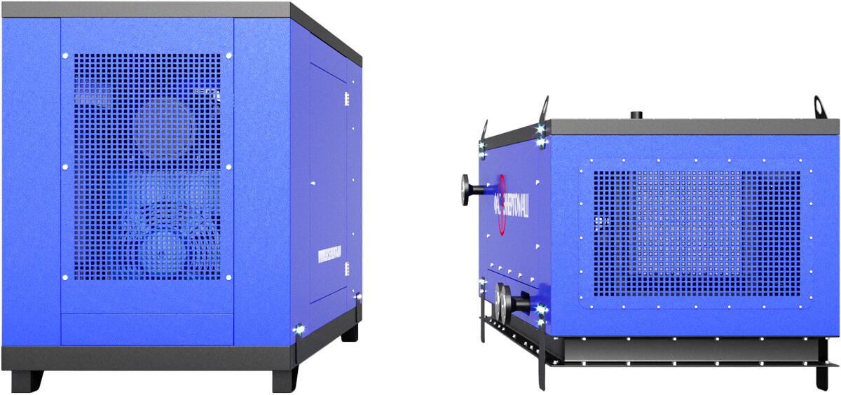
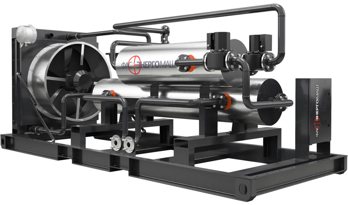
- Thermal Module (TM) of a Standard Factory Configuration. The assembly includes a frame base, two recycling heat exchangers, a bypass pipeline, a gas flow switch, piping, a set of control and measuring devices, and an automatic control cabinet (TM ACC).
- A Separate Thermal Module for Recovery of Exhaust Gases (WGTM). The assembly includes a frame base, an exhaust gas heat exchanger (EGE), a bypass exhaust line, a gas flow switch on the electric drive, and a set of control and measuring devices.
- A Separate Thermal Module for Recovery of Antifreeze (WWTM). The assembly includes a frame base, an antifreeze heat exchanger (AHE), piping, an automatic control cabinet, and three-way valves. In thermal modules, the WGTM and WWTM heat exchangers can be installed both together on one frame and separately. Thus, one of the exchangers can be placed inside a container, and the second — on its roof. Heat exchangers can be located as well on different floors within one energy hub building. It depends on the mode of communication with the mains flows. When ordering any of the modules, the necessary truncated control cabinets can be added to the delivery package.
Basic Package
Standard configuration of a thermal module in a complete factory assembly includes:
- an exhaust gas heat exchanger (EGE);
- an antifreeze heat exchanger (AHE);
- a controlled gas flow switch;
- piping for antifreeze and water lines;
- a bypass pipeline with rotary gates;
- a frame base;
- a complete set of the control and measuring devices;
- an automatic control cabinet (TM ACC).
A heat recovery unit can be additionally equipped with the following components:
- pumps for pumping heat carriers;
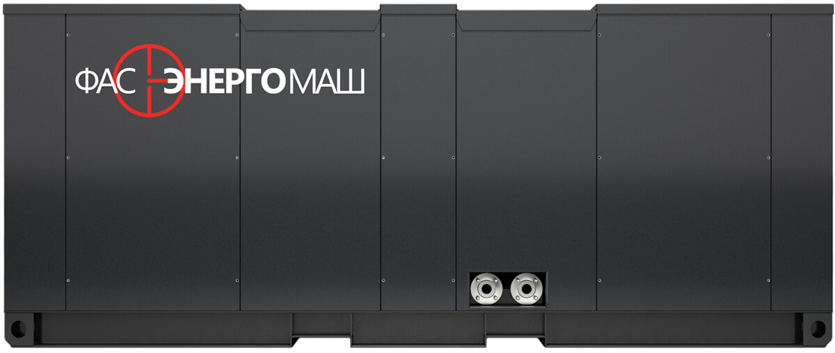
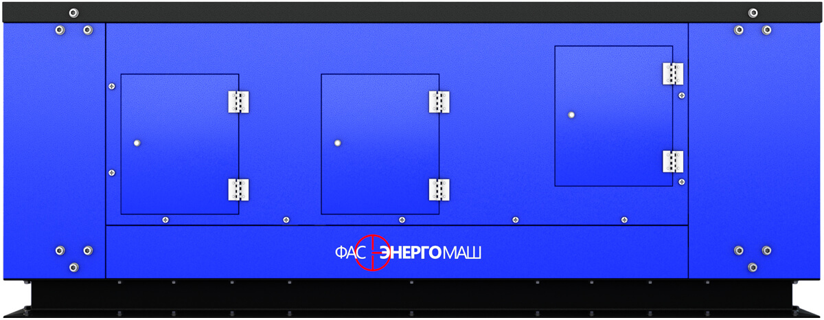
- a thermal module protection in the form of an internal or external casing;
- a low-grade heat recovery system;
- a network heat exchanger;
- an effective noise separator (silencer);
- a flue gas stack.
Advantages and Design Features of FAS Thermal Modules:
- Heat exchangers are made of 12x18h10t stainless steel, which increases the durability of equipments;
- Heat recovery boilers of a fire-tube design are much easier to clean from any contamination and have significantly smaller dimensions;
- EGE has a casing with a compensator, which provides heat exchanger with the necessary protection against damage in non-standard situations;
- An exhaust gas exchanger can be manufactured with a decrease in the level of aerodynamic resistance (up to 2 kPa);
- EGE with a shell-and-tube design is easier to clean and repair under operating conditions in hard-to-reach areas (replacement of gaskets between plates is not required);
- Each thermal module is assembled depending on the conditions of its future operation, taking into account the location of mains and service pipelines. In this case, the dimensions and location of equipment facilitate the connection of module to all necessary communications;
- The operating pressure of liquid in the thermal module makes 0.6 MPa;
- The finished thermal modules, their assemblies and units are subjected to hydraulic tests at a pressure of 0.8 MPa;
- By separate arrangement, it is possible to manufacture modules with operating pressure of up to 4 MPa;
- Our company assists in the development of related systems and the selection of necessary equipment thereto;
- When manufacturing thermal modules, all suggestions and requirements of the customer are taken into account, if they do not contradict the design features of theapparatuses.